Ultrasonic vitrectomy instrument
David Wuchinich
Modal Mechanics
2009 Ultrasonics Industry
Association Symposium
Vancouver, B.C.
©David Wuchinich 2009
Keywords
Ultrasonic, ultrasonic aspiration, ultrasonic surgery, vitrectomy, Gaussian resonator.
Abstract
Contemporary vitrectomy devices utilize an air driven stylus reciprocating within a sheath at a sonic frequency, guillotining and then aspirating the vitreous gel admitted through a distal port in the side of the sheath. A small handheld ultrasonic instrument operating at 50 kHz, utilizing a solid titanium stylus, within a 20 needle gauge sheath, vibrating at an excursion between 150 and 200 microns, has been developed to precisely and rapidly liquefy and aspirate, at 360 mmHg vacuum, vitreous humor from bovine eyes.
Historical preface
Many devices have been developed to surgically remove tissue using the ultrasonic vibration of a hollow tube. Kelman first applied the technology using both irrigation over a tubular tip and aspiration applied to the bore of the tube[1]. His method was successfully applied to extraction of cataracts and is now universally used for this purpose in a surgical procedure known as phaco-emulsification. Wuchinich[2] extended the technology to the removal of tissue, such as brain neoplasms and other tumors, previously resistant to attack from such vibration and then subsequently developed apparatus suitable for use in endoscopic[3] and arthroscopic[4] procedures.
Interest in using the technology to remove vitreous humor from the human eye developed concurrently with the introduction of a device to remove the cataract, but limitations upon the permissible length of the tube and the level of vibration prevented its use in this procedure. The vitreous humor, which is interposed between the lens and the retina, while transparent to light, is subject to various maladies, including macular edema or the presence of blood in the tissue which interferes with visual acuity. In such circumstances, it has been found efficacious to remove that portion of the vitreous so affected. The body eventually replenishes the tissue removed. In 1979, Leitgeb et al[5] published a report of the apparent successful liquefaction of the vitreous humor by a solid stylus vibrating at a frequency of 60 kHz. Their experiments did not seek extraction of the liquefied tissue as it was believed that, as the transformation produced a liquid, ordinary human biological maintenance would ensure its removal and replacement by tissue. Balamuth[6] developed in 1970 devices that used solid vibrating structures to remove tissue by fragmentation and aspiration of the fragmented particles through the interspace between the stylus and a hollow tube surrounding the tip, indicating the feasibility of an alternative form of aspiration that did not require a hollow vibrating tube.
Heretofore, despite Leitgeb and Balamuth’s investigations and instrument development, no ultrasonic device has been developed nor gained medical acceptance to ultrasonically extract vitreous. The diameter and length of a slender stylus that will sustain axial (a direction parallel to the length dimension of the stylus) ultrasonic vibration along its length of the magnitude necessary to cause liquefaction has eluded practitioners. Thus, contemporary technology does not employ ultrasonic vibration, using instead the sonic vibration of a tip traveling inside a hollow tube provisioned with a hole in its wall near the end of the tip.
Figure 1 illustrates the procedure as now practiced.
Vitreous tissue, a gelatinous-like tissue, is forced partially into this hole by hydrostatic pressure applied to the vitreous humor through hypodermic infusion of fluid into the vitreous compartment of the eye. The vibrating tip repeatedly slices off the tissue protruding through the hole and vacuum applied to the tube draws the tissue so dissected into a receptacle.
As has been demonstrated with phaco-emulsification, ultrasonic technology, however, promises the advantage of producing less trauma in the eye than conventional methods and, given both Balamuth’s and Leitgeb’s work, appears to be possible if unique ultrasonic design innovations are brought to bear upon the problem. In particular, experiments by the author have shown that if a solid metal stylus, surrounded by a hollow tube, can be developed that is at least 30 millimeters in length and no more than 0.7 millimeters in diameter and capable of sustaining a longitudinal vibratory excursion at its point of tissue contact of at least 50 microns, then surgical liquefaction and aspiration of vitreous in-vivo is feasible.
Instrumentation
Figure 2 illustrates the elements of the instrument.
The transducer generates an ultrasonic vibration that is communicated to a removable tip. The tip itself is solid and surrounded, except at its free end, by a stationary sheath that is removable but, in use, forms part of the transducer housing. The tip is inserted into the eye, replacing the vitrectomy cutter shown in Figure 1. All other instrumentation shown in Figure 1 remains operational. The tip is vibrated within the surrounding sheath whose terminus is closed, liquefies the vitreous, drawn into the sheath through an opening in its side wall, in the region immediately about the free end of the tip and vacuum applied to the interspace between the tip and the sheath removes the vitreous so liquefied from the operative site.
The transducer shown is of conventional and well established design known in the art, derivative of a Langevin7 sandwich, named after its inventor, who produced the first known such structure in 1917, using either disks or a tube made of piezo-active material that changes its length is response to the application of an electric or magnetic field. The particular configuration shown here is a refinement invented by Shoh8 to improve mechanical integrity under substantial vibration. The material is subjected to quiescent compression provided by a pre-stressing compression nut so that the parts of the mechanical assembly remain in intimate contact during vibration. The length of piezo-active material and its associated pre-stressing components comprise at the design frequency a one quarter wavelength section with a node of motion located as indicated on the drawing. A second quarter wavelength section is integrally joined to the assembly at the node and serves to amplify somewhat the excursion produced by the transducer during vibration. The transducer, including the piezo-active material, pre-stressing components and quarter wavelength motion amplifying section comprise a composite rod designed to resonate at a predetermined frequency such that its ends move in opposite axial direction with a point of no motion located at the node.
Attached to end of the amplifying section is a second half wavelength resonator which further amplifies the end motion of the quarter wavelength section of the transducer. This second resonator is designed as a variant of the common stepped horn described by Balamuth9 in 1954. Such resonators are typically made of a prismatic solid having two different cross sectional areas, one for the first quarter wavelength and the other for the
second quarter wavelength section. As such, motion imparted at the resonant frequency to the first section is amplified by the second according to the relation
S1/S2 (1)
where the subscripts 1 and 2 refer to the first and second sections respectively. The resonant frequency of such a structure remains the simple expression for that of a uniform rod:
![]() (2)
(2)
where ¦ is the frequency, c the extensional sound velocity in the material and l the rod’s overall length.
The second section is the surgical implement of the invention. It is this section, enclosed in a stationary sheath and exposed to tissue only at its terminus, that is inserted into the eye, replacing the vitrectomy cutter shown in Figure 1. As Equation 2 reveals, the length of the second resonator is a function of frequency, but, in general, the length of any resonator, including such composite constructions as the transducer, is also inversely proportional to the resonant frequency. Vitrectomies are performed today with the assistance of an operating microscope and the procedure itself is termed micro-surgical. Dexterity is essential and ease of manipulation of the instruments essential for successful extraction of the vitreous humor. Such requirements dictate that the instrument, which in this case is the handpiece, be kept small enough to fit within the span of and be easily controlled by the surgeon’s fingers. If this span is therefore limited to a 6 or 7 centimeters, then, using titanium which is a metal of which most surgical ultrasonic components are made and which has a sound velocity of about 500,000 centimeter per second, Equation 2 dictates that the resonant frequency must be at least 40,000 Hz.
However, if the tip is made as a simple stepped titanium resonator the length of the second section (and the first for that matter) will be 31 millimeters. The human anatomy requires at least such a length to reach all parts of the vitreous compartment and when other considerations are taken into account, such as the fittings of the protective sheath about the tip and seals for aspiration, a length significantly less that 31 mm will be available for surgical use. It is therefore of interest to use a design that offers a greater length for the second section.
Of interest, as well, is a limitation upon the maximum excursion that titanium can withstand at any given resonant frequency. It has been found when using ultrasonic surgical devices that tissue excision requires a minimum velocity of the tip’s free and tissue contacting end and that, in general, the greater this velocity beyond the minimum value needed the greater is the rate at which tissue is excised. At any given specified resonant frequency, the tip excursion, which is the total of the back and forth movement of the tip, is related to the frequency as:
s = no /p¦ (3)
where s is the excursion and no is the tip’s peak free end velocity. It can be shown that for a rod of constant cross sectional area the peak stress occurs at the node of motion, which is located at the center of the rod, and that it is related to free end excursion as
![]()
![]() (4)
(4)
where s is the stress, r is the density of the material, c the extensional sound velocity and the free end velocity.
There is limit to value of s for all materials. In particular, it has been found that titanium can indefinitely withstand stresses that cyclically vary from tensile to compressive up to 275 Mpa (40,000 pounds per square inch). Hence, there is a definite limit to the value of no and, by Equation 3, to s. Equation 4 also applies to a quarter + quarter wavelength stepped horn. For titanium then, with a density of 4430 Kg/m3, an extensional sound velocity of 5080 m/s and a frequency of 40 kHz, the maximum excursion s, can be computed to be about 100 microns. To further increase this excursion a departure in design must be taken that modifies the shape of the second quarter wavelength section.
For a quarter wavelength resonator having a uniform cross sectional area, the stress diminishes from a maximum value, occurring at the node, until it vanishes at the free end according to the relation
![]() (5)
(5)
where x is the distance measured from the node to a point on the section.
It is possible, however, to progressively change the cross sectional area of the second quarter wavelength section of the tip such that the stress remains constant throughout the length10. Such an alteration allows the length of the second section to be made indefinitely long and to be capable of indefinitely large excursions, although, in practice, the cross sectional area becomes at some point so small that it defies fabrication or the portion of the tip so affected becomes too fragile to sustain normal use in surgical procedures. A section having the property just described is known as a Gaussian tip as the diminution in cross section area contains the Gaussian mathematical function. Wuchinich3 has described the design of such resonators for use in endoscopic surgical applications.
To extend the length of the second section of the vitrectomy tip so that it becomes long enough for use in reaching the entire vitreous compartment of the eye in handpieces operating at frequencies extending from 40 kHz, a portion of the tip is tapered to produce constant stress until the overall length of the section exceeds 30 millimeters,
with the added benefit of a significantly larger permissible excursion than is possible using a section having a uniform cross sectional area.
In-vitro Tests
To determine the effectiveness of vibration in liquefying vitreous, bovine eyes were obtained and the vitreous exposed by manual dissection. The instrument shown in Figure 2 was attached to vacuum pump and ultrasonic generator. The vibration amplitude, measured using a 300 power microscope fitted with a calibrated reticule, as an excursion of the end of the tip in a water bath (sheath removed), was adjusted to approximately 100 microns peal-peak using the generator controls. The frequency of vibration was also recorded to be approximately 50 kHz. A photograph of test arrangement and equipment is reproduced in Figure 3.
With the sheath in place and the vacuum level, measured when aspirating clear water through the side port of the sheath, was adjusted to 380 mmHg, the tip was applied to the exposed vitreous. Liquefaction and aspiration occurred immediately. There was no observable production of bubbles or turbulence of the parent tissue during these tests. The rate of removal was not measured, but a video recording was made of one test, allowing a necessarily approximate estimate of the aspiration rate to be in the neighborhood of 1 cc/minute.
David Wuchinich
Director
Modal Mechanics
Yonkers, New York
June 10, 2009
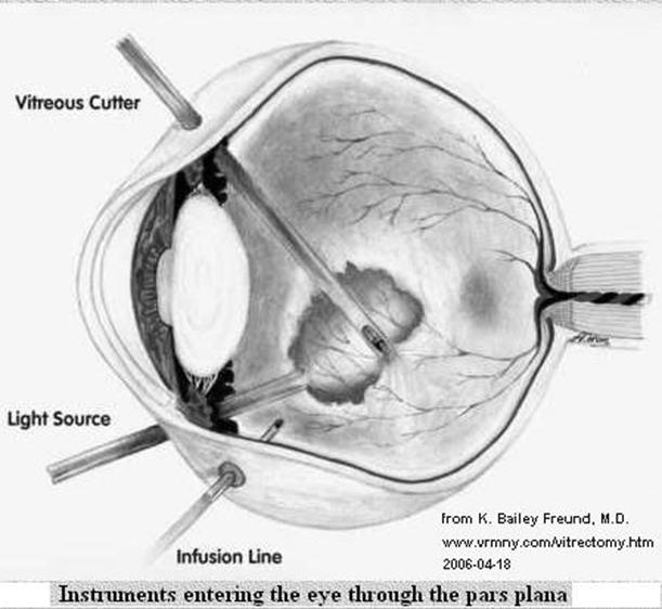
Figure 1 - Vitrectomy Procedure
 Figure 2
Ultrasonic Vitrectomy Instrument
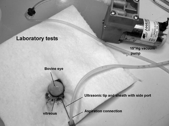
Figure 3 – Invitro vitrectomy of bovine eye
References